
Welcome to Part 2 of our “PLC Hacking series”. In our previous blog, we covered setting up our Koyo CLICK PLC and writing our first ladder logic program into the PLC. Here, we are going to learn about overriding PLC data from remote sources and discuss how different industrial communication protocols like Modbus TCP and Ethernet/IP do not have inherent security.
As of now, our CLICK PLC only reacts to localized input. For it to react to remote inputs, we need to have overrides enabled. The following steps demonstrate how to do that.
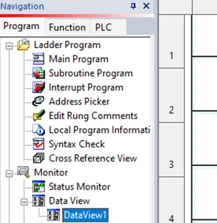
Open DataView1 on the Navigation pane on the left side.
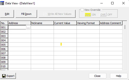
Then, we’ll proceed to select the address by clicking the Address button on the right-hand side, as shown in the following screenshot:
A dialog box will appear, allowing us to select an address from the list of addresses available on Koyo Click.
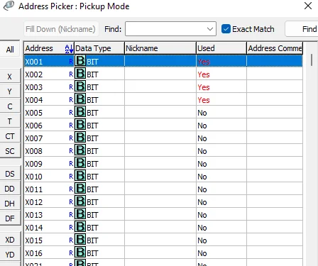
Double-click the first address; that is, X001 and click OK.
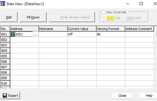
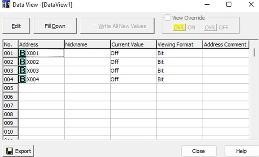
Perform this step for all the 4 inputs X001-X004. The final Data View should look like the screenshot below.
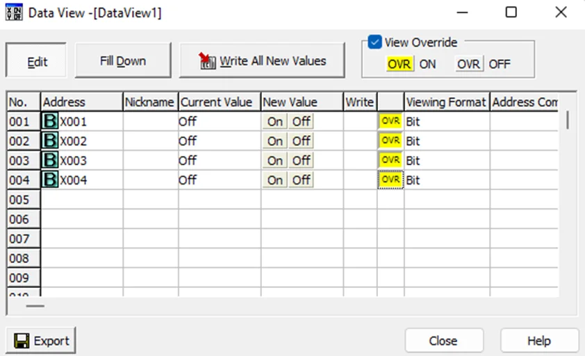
Now, click the Edit button and tick the View Override box.
Double-click the OVR buttons on the same rows as X001-X004. It should now be the color yellow as shown below.

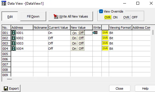
Double Click the ON button for X001 in the New Value column. We should hear the coil energizing on the PLC and visually see the lights enabled on it.
Double Click the ON button for X001 in the New Value column. We should hear the coil energizing on the PLC and visually see the lights enabled on it.
Modbus is a serial communication protocol that was published in the 1970s as a means of connecting equipment in an industrial process over a common bus. This protocol is the most widespread one within ICS. Modbus is a clear text protocol with no authentication. It works in a Master / Slave mode. This means the Master has the pull the information from a Slave at regular times. A Modbus network can have a maximum of one master and 247 slaves.
In our case the PLC acts as a Modbus slave. Mbtget is a simple modbus/TCP client write in pure Perl. We can use mbtget from our kali linux, which acts as the Modbus master.
We can read coil bits using the -r1 flag. -a flag specifies the address and -n flag defines the number of consecutive values to be read from the starting address.

Mbtget can also be used to write bits into the PLC using the -w5 flag. We are going to write a bit value of 1 to address 0 using the following command.

On reading the PLC values again, we see that the bit value at address 0 is now 1.

As we have seen, it was easy to randomly set a bit with a simple command-line tool. There was no authentication mechanism in place and the messages are sent in plain-text without any encryption. Next, we’ll look at Ethernet/IP.
Ethernet networks were used successfully in manufacturing environments by the early 1990s. Ethernet/IP is a communication network designed for use in industrial environments and time-critical applications. Common Industrial Protocol (CIP) messages are the core element that powers Ethernet/IP. It is the object-oriented and open nature of CIP that has allowed quick adoption in the market.
We are going to learn a bit about unconnected explicit messaging, which is a message format in Ethernet/IP which we are going to use for interaction with our PLC. Explicit messaging uses a format called Lpacket, inside of which reside service fields. Service fields are as follows:
For more info on Ethernet/IP, Click here
The Ethernet/IP adapter on our PLC is not enabled by default. We have to enable it using the CLICK programming software. To do this, first we need to navigate to the setup tab and click on Ether/IP button.

This will bring up the following window.
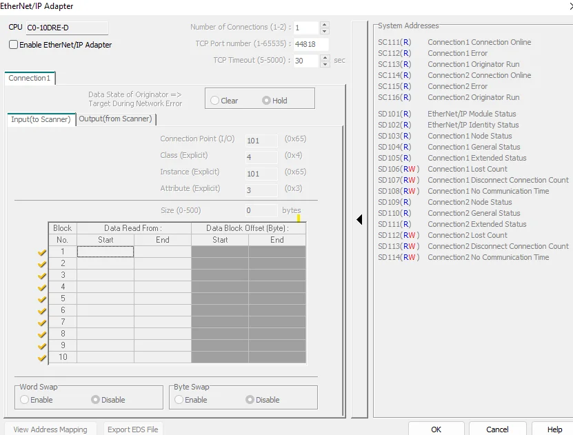
Select the Enable Ethernet/IP Adapter checkbox in the window. This will enable the selection and editing of options in the window. We’ll focus on the Input (to Scanner) and Output (from Scanner) data blocks. The Ethernet/IP master reads the input blocks. Select XD0 for the start of block 1 and do the same for the end address of block 1 but select XD8. Your addressing should look like the following screen
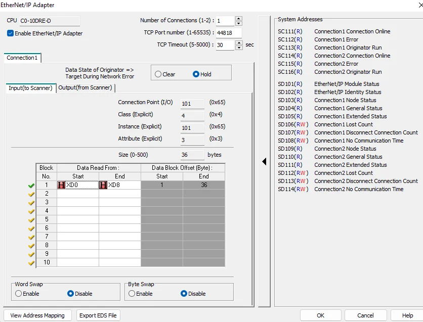
Take a note of the Input Class ID, Instance ID and Attribute ID (4/101/3). Next, we want to set the same for our Out (from Scanner) block addressing, but instead of using XD addresses for Start and End, we will use YD addresses. Once finished, it should look like the following screenshot:
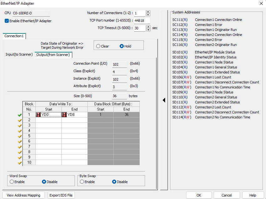
Take a note of the Output Class ID, Instance ID and Attribute ID (4/102/3). Now, we have to write our project to the Koyo CLICK.
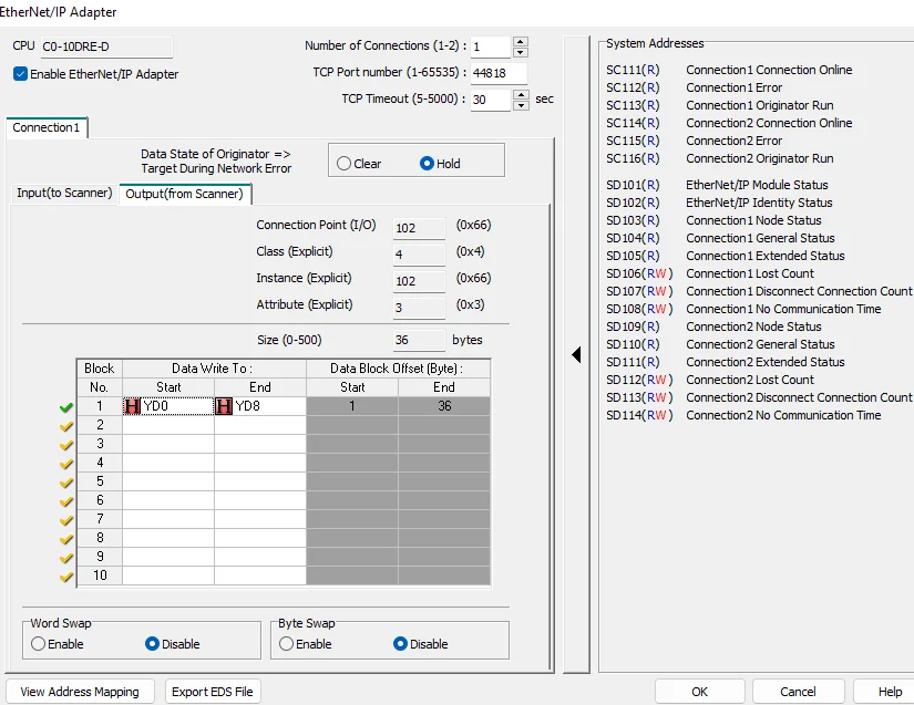
After that, we can move to our Kali Linux machine. We are going to use the cpppo python package for Ethernet/IP communications. To install this module, run the following command:
pip3 install cpppo
Now, we’ll have to run the following command.
python3 -m cpppo.server.enip.list_services -vv -a 10.0.1.10 --list-identity
We should get a long output like the following.
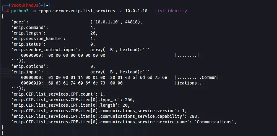
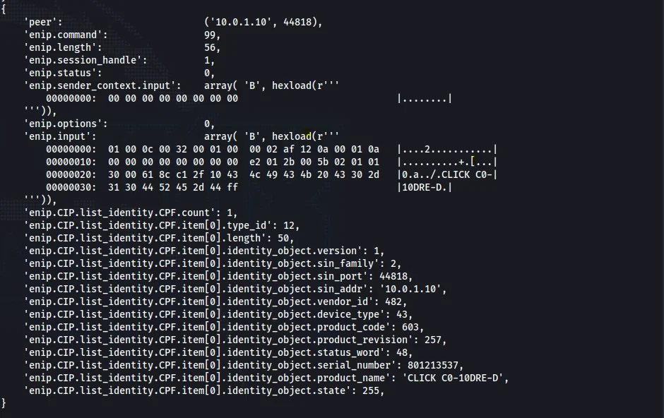
We were able to discover the identity of the PLC as ‘CLICK C0-10DRE-D’.
During setting up our PLC Ethernet/IP Settings, we took a note of our Input and Output class, Instance and attribute IDs.
We now have enough information to interact with our program running on our PLC. As a way to monitor how commands are interacting with the PLC, we want to add a little configuration to the Data View screen in our Koyo CLICK programming software. See the following screenshot, and we will quickly step through the actions that should be taken to set this up for monitoring:
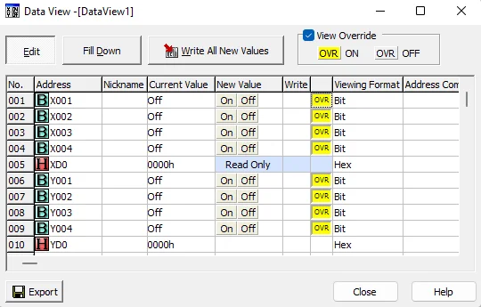
Note that the XD input registers are read-only while the YD output registers are read/write.
Now type the following command on our Kali Linux machine:
python3 -m cpppo.server.enip.get_attribute '@4/101/3' '@4/102/3' -S -a 10.0.1.10
This command uses simple mode with the -S flag to get the attributes located in these objects.
We should get the following response if all our inputs and outputs are off.

Now we are going to write values to the output YD registers directly using the following command:
python3 -m cpppo.server.enip.get_attribute '@4/102/3=(INT)15' -S -a 10.0.1.10

Our PLC’s output lights Y1-Y4 should have lit up now. To verify whether the output registers have changed, we can use the following command:
python3 -m cpppo.server.enip.get_attribute '@4/102/3' -S -a 10.0.1.10

Also check the Data View screen. All the outputs should now be ON.
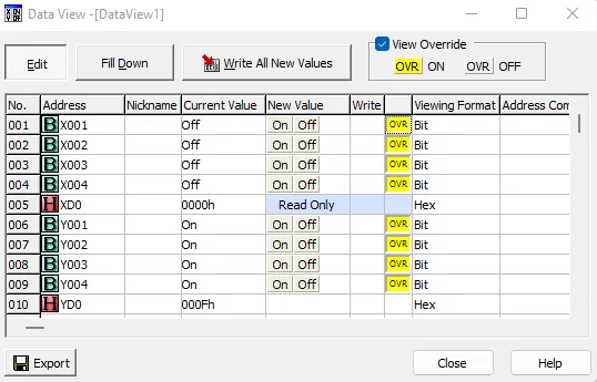
We were able to turn the lights ON and OFF by simply sending unconnected explicit messages to the PLC. We didn’t have to do anything regarding security to simply send Modbus TCP and Ethernet/IP commands to our Koyo CLICK PLC.
Due to the insecure nature of PLCs, security boundaries have to be built around the ICS network mostly by using strict firewall configurations and by implementing an architecture similar to the Purdue reference model. The end goal here is to air-gap the IT and OT networks. We’ll delve more into PLC hacking techniques in upcoming blogs. Stay connected with Redfox Security for more updates.
Redfox Security is a diverse network of expert security consultants with a global mindset and a collaborative culture. If you are looking to improve your organization’s security posture, contact us today to discuss your security testing needs. Our team of security professionals can help you identify vulnerabilities and weaknesses in your systems and provide recommendations to remediate them.
“Join us on our journey of growth and development by signing up for our comprehensive courses.“