
Programmable Logic Controllers (PLCs) are industrial computers used to control different electro-mechanical processes for use in manufacturing, plants, or other automation environments. PLCs can range from small modular devices with tens of inputs and outputs (I/O) in a housing integral with the processor, to large rack-mounted modular devices with a count of thousands of I/O, which are often in networks containing other PLC and SCADA systems. Programmable Logic Controllers help in the functioning of critical infrastructure. They have been widely adopted as high-reliability automation controllers suitable for harsh environments.
Even though PLCs are used on mission-critical applications such as nuclear power plants, they were not designed with cybersecurity in mind. An example of an ICS attack is Stuxnet, which targeted the nuclear program of Iran. The industrial cybersecurity industry has grown significantly in recent years. More industries are following the Purdue Model for segmenting the Operational Technology (OT) Network from The Informational Technology (IT) Network to improve their cybersecurity posture. More information regarding the Purdue model can be found here.
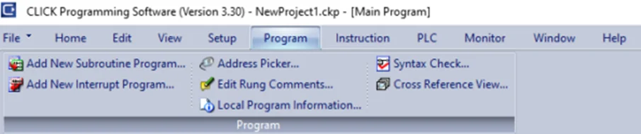
In our “PLC Hacking” series, we are going to cover different methods of interacting with PLCs, the different protocols which they use, and to demonstrate their inherent lack of security protection. In this particular blog, we will be looking at setting up the PLC and writing a ladder logic program into it.
Power up the Programmable Logic Controllers using a 24V 2A DC power supply. Wire up the Windows PC and the PLC to the switch. Also, set the network interface on Kali Linux’s VirtualBox settings to “Bridged Mode”. Then, download and install the free CLICK software on the Windows machine. After installation, we see the following screen on opening the application.

Click on “Connect to PLC”. We will now be presented with the following screen:
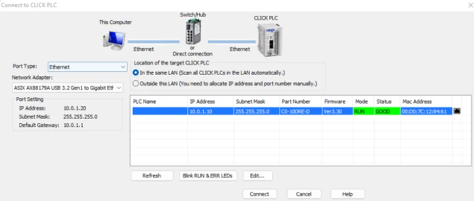
Make sure that the Programmable Logic Controllers , Windows PC, Switch and Linux VM are on the same subnet.
For example, assign the following static IP addresses on a 10.0.1.0/24 subnet.
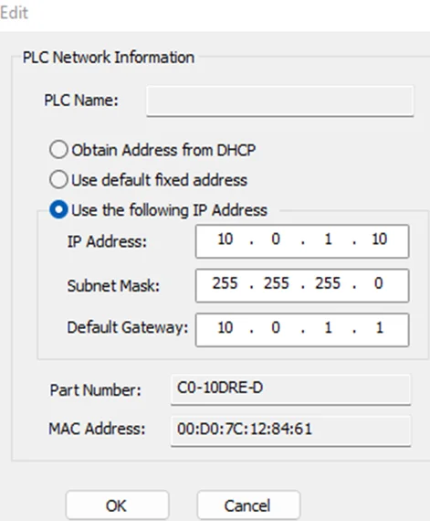
If the subnet of the PLC does not match, click the “Edit…” button (see screenshot above), and assign the preferred IP. It should look similar to this.
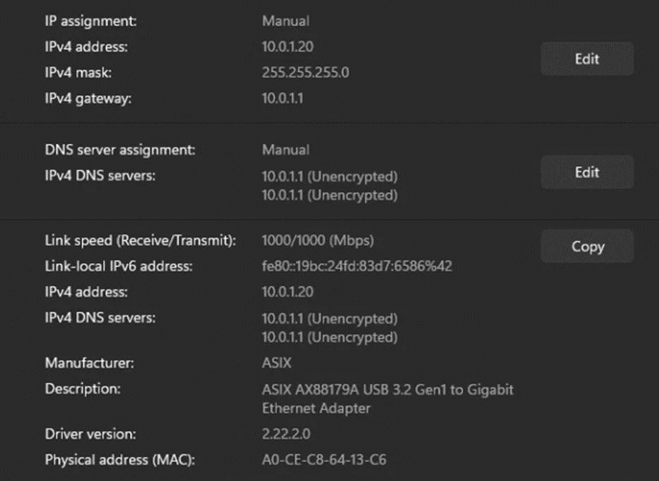
The network settings on our Windows machine are shown below.
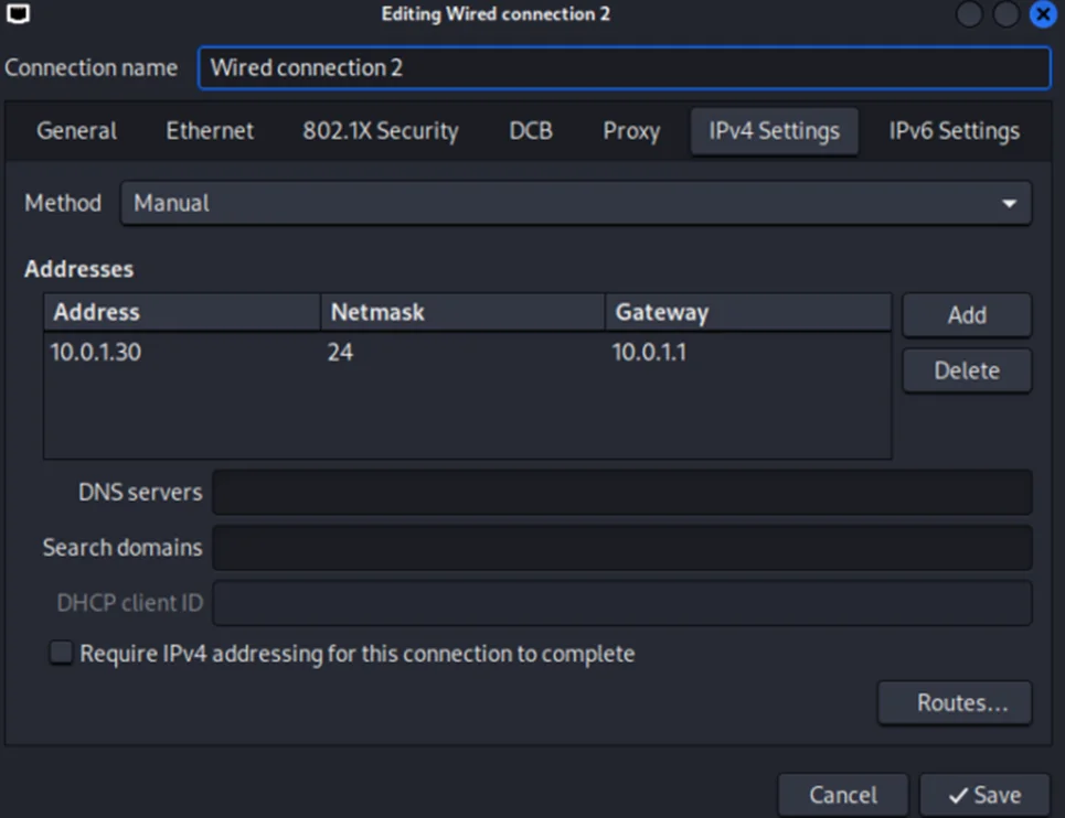
Kali Linux’s network settings are shown below:
Now, we’ll proceed with connecting to the PLC.
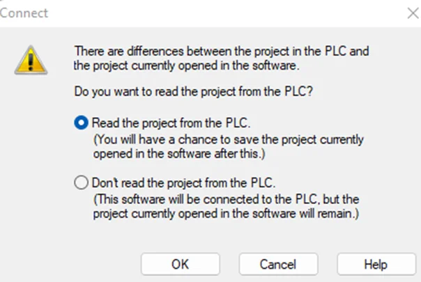
Select “Read the project from the PLC” and press “OK”. This option will read the current project from the PLC if any.
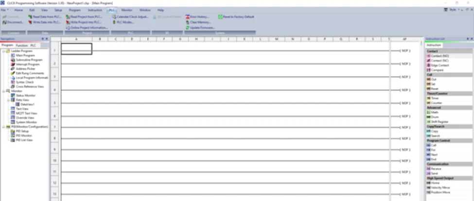
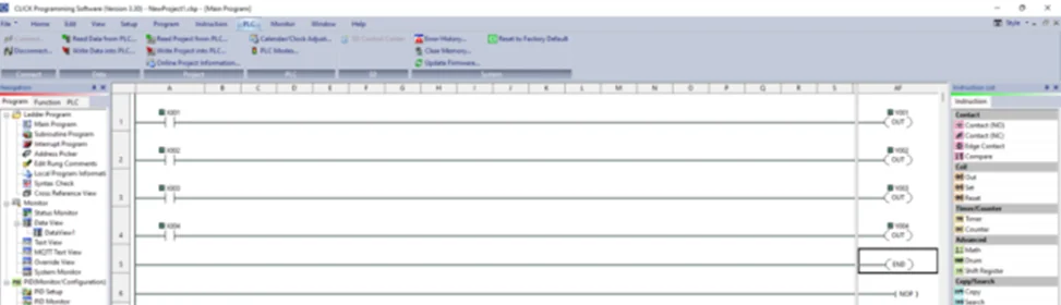
A new project should look similar to the screenshot below.
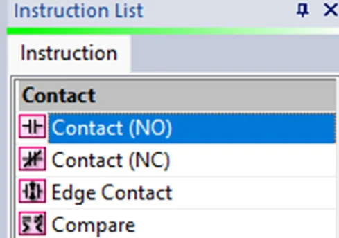
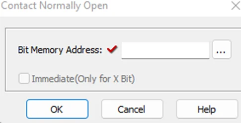
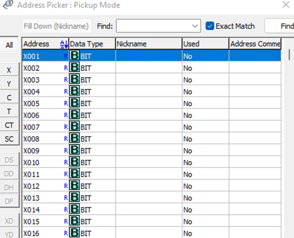
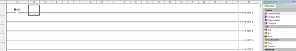
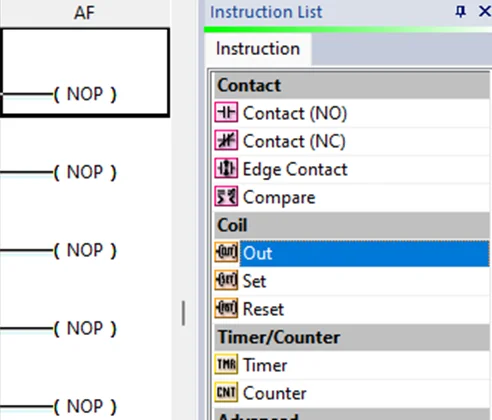
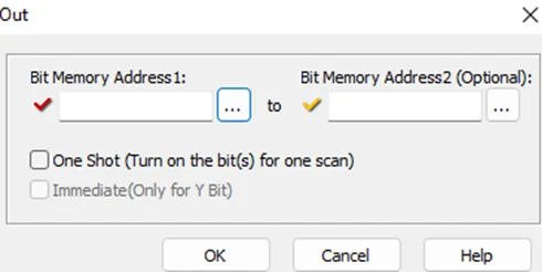
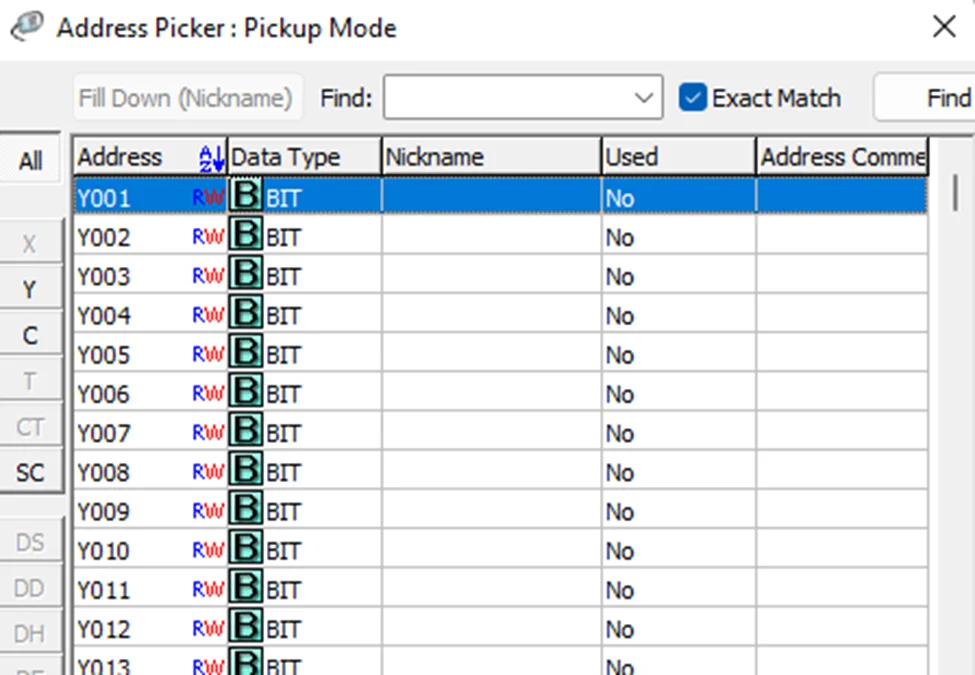
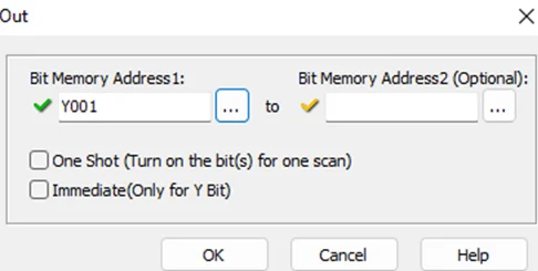
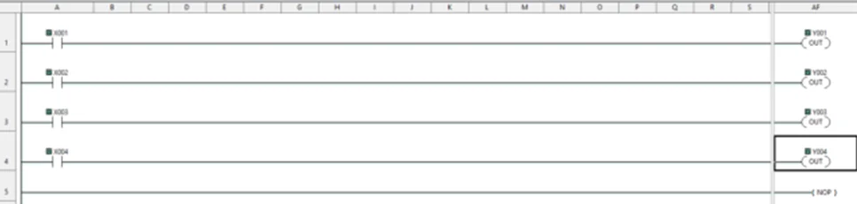
Now, we’ll be performing a bit of PLC programming using Ladder logic. We’ll create a simple program that allows us to push buttons and turn on lights. A ladder diagram represents a control program in an electrical wiring framework. The power sources are the vertical lines (ladder), while the control circuits are the horizontal lines (rungs).
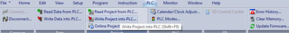
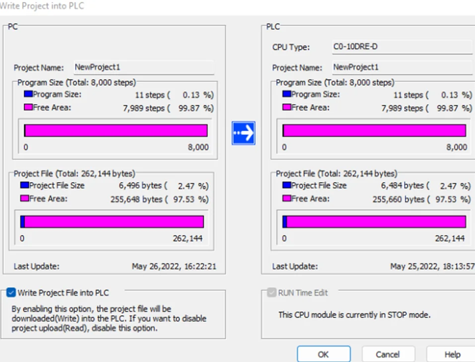
To write the project to Programmable Logic Controllers , select the “Write Project into Programmable Logic Controllers” option from the PLC menu, as shown in the following screenshot.
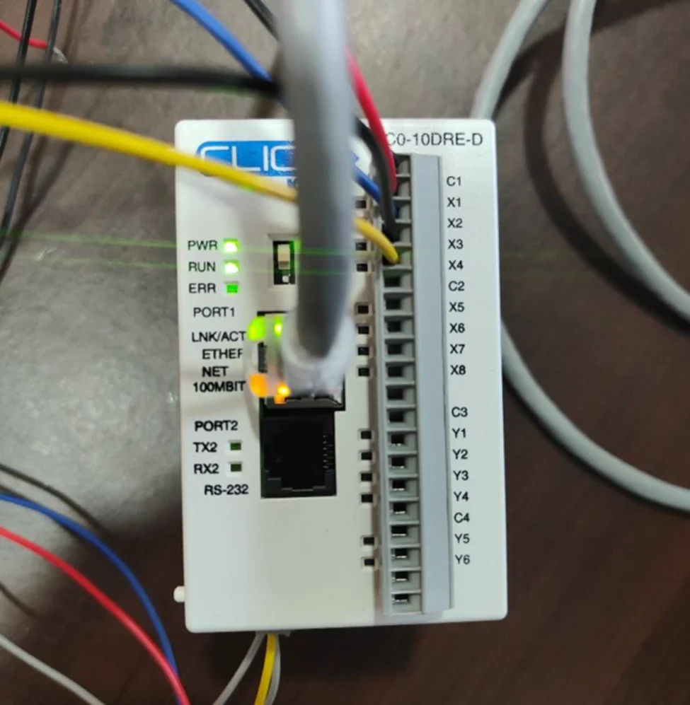
In this blog, we learned how to setup a connection with the Koyo CLICK PLC and to write a basic ladder logic program. We wired up X1-X4 inputs and observed how outputs Y1-Y4 lights up respective to their inputs. In our PLC Hacking Part 2 blog, we will delve into overriding data and how to interact with the PLC using industrial communication protocols like Modbus TCP and Ethernet/IP.
Redfox Security is a diverse network of expert security consultants with a global mindset and a collaborative culture. If you are looking to improve your organization’s security posture, contact us today to discuss your security testing needs. Our team of security professionals can help you identify vulnerabilities and weaknesses in your systems and provide recommendations to remediate them. To schedule a call with one of our technical specialists, call 1-800-917-0850 now.
“Join us on our journey of growth and development by signing up for our comprehensive courses.“


Redfox Cyber Security Inc.
8 The Green, Ste. A, Dover,
Delaware 19901,
United States.
info@redfoxsec.com
©️2025 Redfox Cyber Security Inc. All rights reserved.