
Electronics can be a challenging world, especially when working with UARTs, which makes understanding its inner workings essential. Unlabeled UART pins can present both beginners and experts with challenges; this user-friendly guide will walk you through identifying Ground (GND), Power (VCC), Data Reception (RX), and Transmission (TX) pins with the aid of multi meter measurements and Arduino’s integrated development environment (IDE).
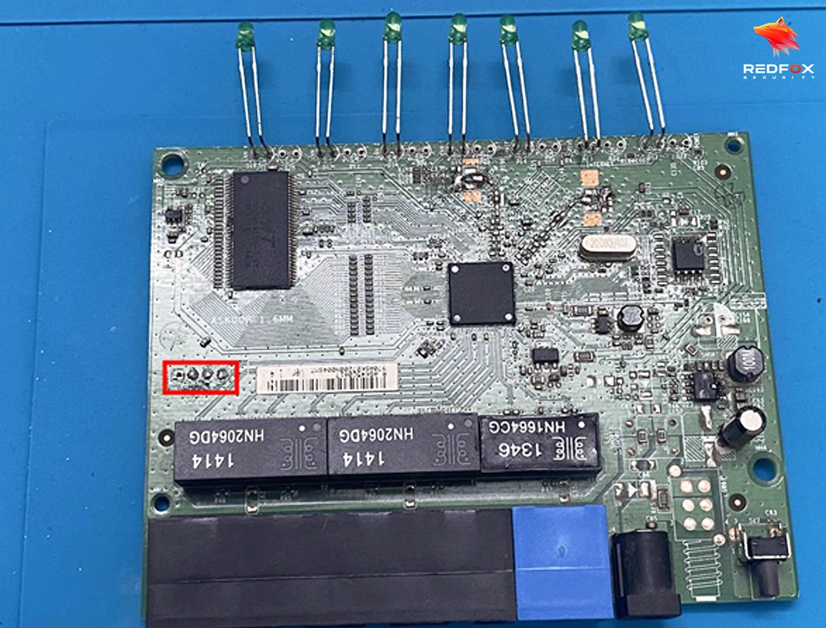
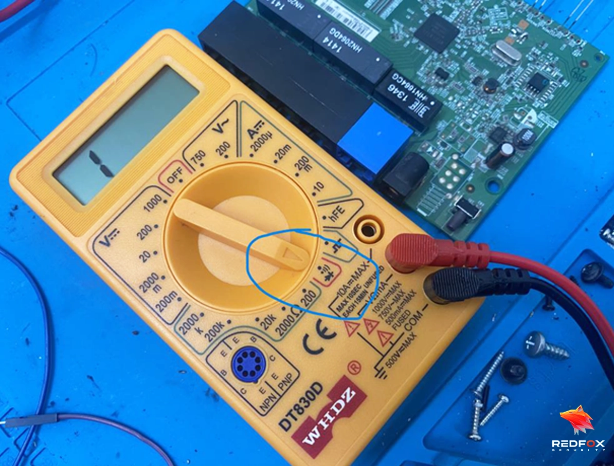
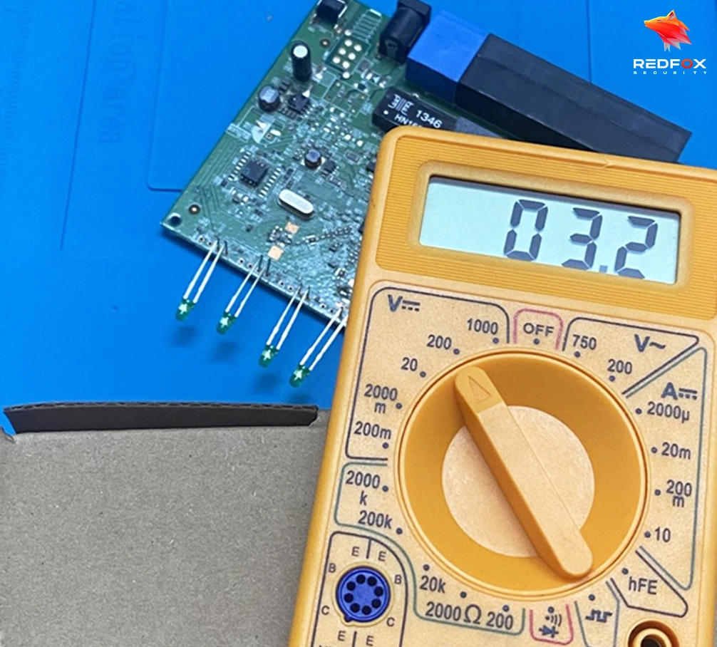
RX and TX pins play an essential part in creating and maintaining communication between devices using the UART protocol. They ensure seamless data transfer, making them essential components in various electronic systems and applications.
Employ the Arduino IDE to upload a program designed for toggling multiple pins, as exemplified below.
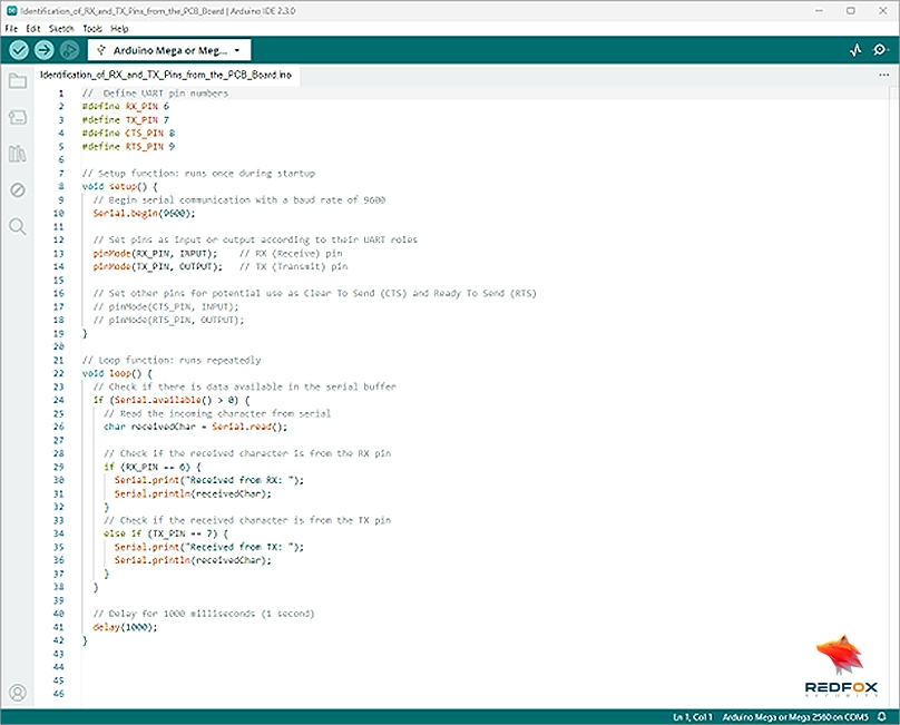
Connect GND to Arduino’s GND, and test pins for RX/TX.
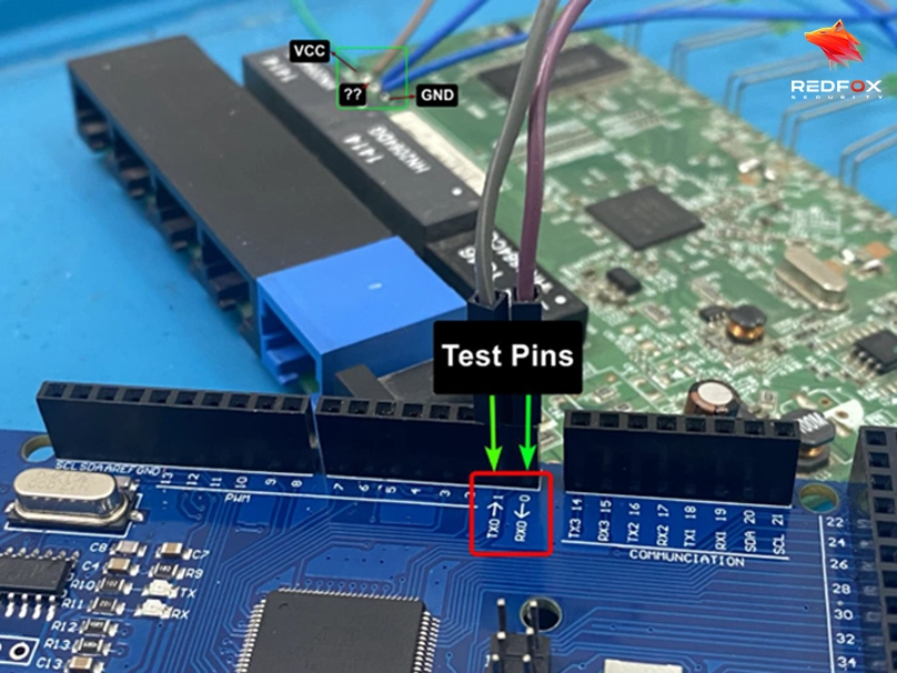
Check connections: Inspect and fix any loose wires or misplaced components to ensure smooth data flow in your Arduino project.
Adjust serial settings: Confirm proper baud rates and communication parameters for better compatibility between your Arduino and computer
Improper connections may cause gibberish data in Arduino Serial Monitor.
Monitor Serial Output: Connect GND to Arduino’s GND, and test pins for RX/TX. Improper connections may cause gibberish data in Arduino Serial Monitor.

When encountering gibberish data in the Integrated Development Environment (IDE) while working with a microcontroller or microprocessor system, swapping the RX (Receive) and TX (Transmit) connections can often resolve the issue and provide the desired, relevant data.
By interchanging the RX and TX pins, the system can correctly interpret the incoming data, ensuring smooth communication between the device and the IDE. This simple step promotes a more efficient debugging process and enables the user to obtain accurate information for further analysis and development.

The detection of a signal being received on the RX pin indicates a probable UART communication, as it signifies the presence of a relevant signal.
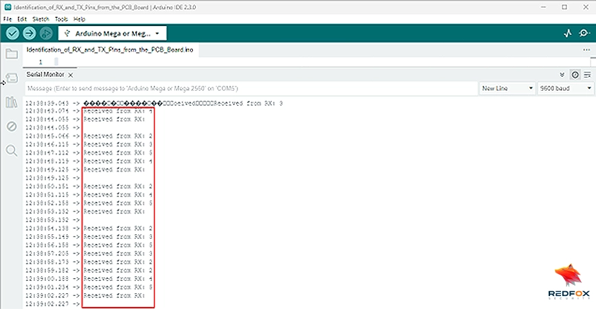
Troubleshooting and resolving common issues are essential steps in ensuring a smooth process of identifying UART pins using a multimeter and Arduino. If you encounter unstable voltage readings, it’s crucial to verify proper connections and maintain a stable power supply.
In cases where there’s no data flow in the serial monitor, a thorough check of wiring, connections, and Arduino code is recommended. To enhance your experience, consider incorporating some helpful tips and best practices, such as double-checking connections before testing, using color-coded wires for easy identification, and opting for simple Arduino code during initial testing.
By addressing potential challenges and implementing these suggestions, you’ll significantly improve the efficiency and accuracy of your UART pin identification process.
Redfox Security is a diverse network of expert security consultants with a global mindset and a collaborative culture. If you are looking to improve your organization’s security posture, contact us today to discuss your security testing needs. Our team of security professionals can help you identify vulnerabilities and weaknesses in your systems and provide recommendations to remediate them.
“Join us on our journey of growth and development by signing up for our comprehensive courses.”