
In the world of smart devices, IoT devices are becoming more vulnerable to attacks. Hardware hacking is a technique used to exploit IoT devices at the hardware level. One method is UART, a communication protocol used in many IoT devices. By gaining access to UART, attackers can bypass security and gain control over the device’s operating system. This article explores the basics of hardware hacking for IoT devices, focusing on UART-based attacks. Manufacturers need to prioritize hardware security to protect against these types of attacks in our interconnected world.
In this article, we employ a router to access the Command Line Interface (CLI) and delve into the interface’s functionalities.
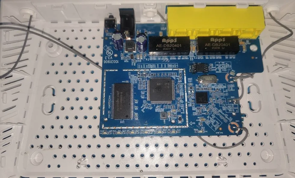
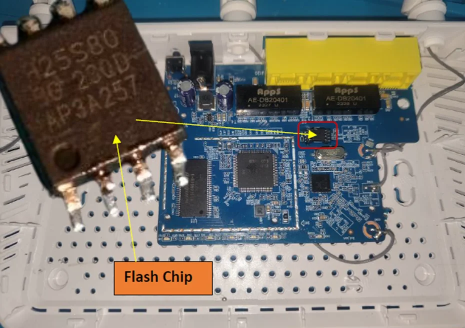
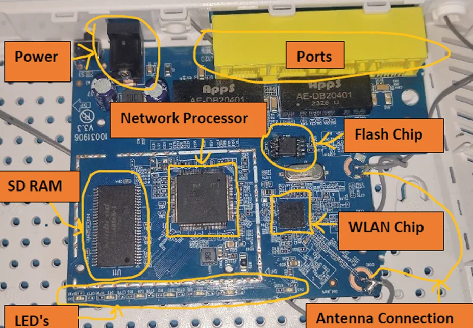
Displayed below is a front view of the router after disassembling it with a screwdriver and pry tools:
The rear side of the router is depicted, showcasing the antenna wire and the absence of other pinouts and chipsets:

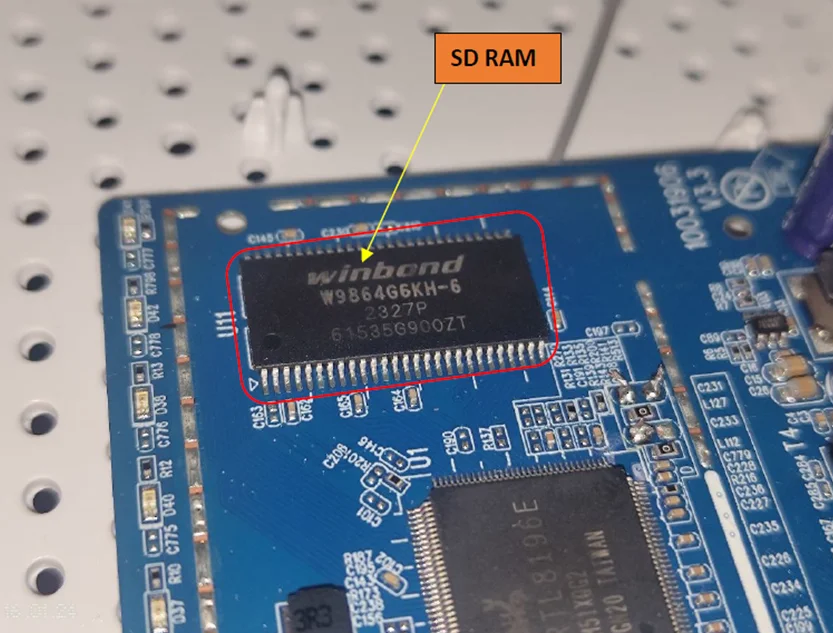
SDRAM:
In the image below, the SDRAM is clearly visible which is Winbond SDRAM Memory IC 64Mbit Parallel 166 MHz 5ns 54-TSOP.
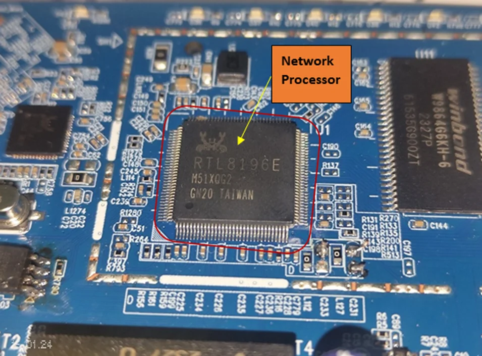
CPU:
The chipset provided is the RTL8196E, belonging to the Realtek RTL8196E family. This chipset seamlessly combines a powerful 400MHz RISC CPU, a five-port Fast Ethernet switch featuring PHY, SDR, DDR memory controller, flash memory controller, USB2.0 controller, and practical peripheral interfaces. Engineered for 802.11n AP router applications, the RTL8196E excels in delivering high performance while maintaining low power consumption.
Features
Memory
Interfaces
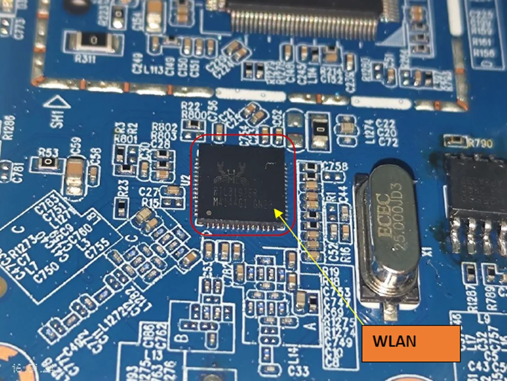
WLAN Chip:
The Realtek RTL8192ER-CG is an 802.11bgn 2.4G single-chip that integrates Wireless LAN (WLAN) and a network PCIe controller. It combines a WLAN MAC, a 2T2R capable WLAN baseband, and WLAN RF in a single chip. The RTL8192ER-CG provides a complete solution for a high-throughput performance and low-power consumption integrated wireless LAN device.
Features
Applications
This chip is used in TVs, Set-Top/Over-The-Top boxes, IP cameras, as well as WI-FI appliances such as this router.
Flash Chip:
The chip identified is the EEPROM H25S80 BG 23QD AP3A257.
Hardware Object Purpose Serial
Test Pins:
If we examine the router’s PCB, there are no apparent pads intended for debugging or reversing the router. However, on the back, there seem to be some available pads, possibly meant for testing the router during manufacturing.
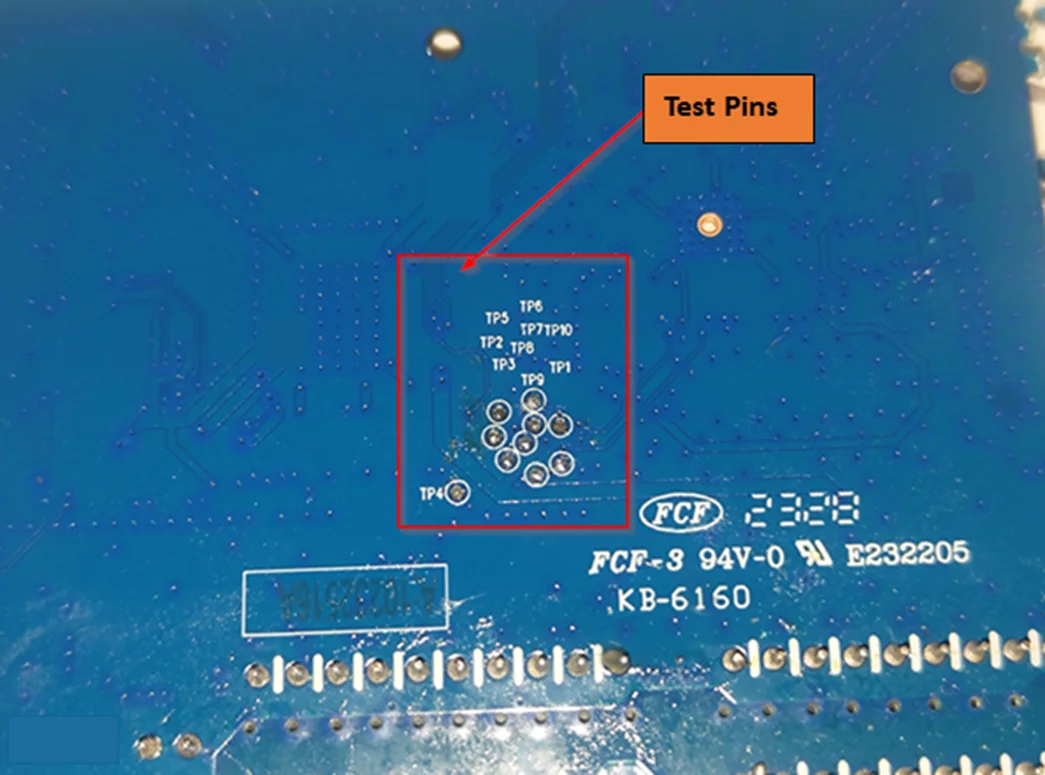
Test Pins
Now, the next step is to identify the specific purpose of each pin among the available test pins. To achieve this, we’ll utilize a piece of hardware called JTAGulator. This is a brute-force toolkit designed to systematically test pins and determine their usage, such as identifying pins associated with protocols like UART, JTAG, and others.
Initially, we require a soldering machine to delicately solder each pin, ensuring there is no unintended short circuiting with neighboring pins.
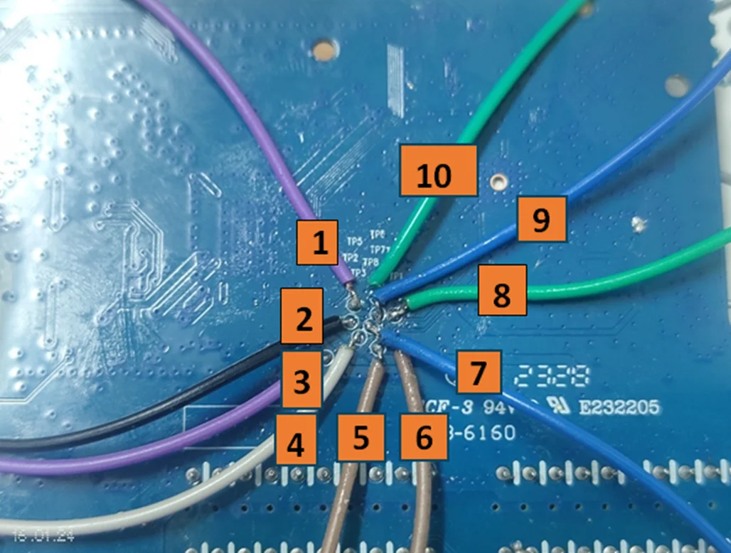
Wires Soldered
Next, establish connections from each pin to the JTAGulator, starting from Channel 01 and extending to Channel 09. This encompasses a total of 10 pins, potentially associated with protocols such as UART, JTAG, SWD, and I2C.
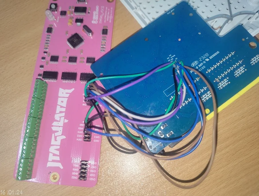
Connection with PCB and JTAGulator
To facilitate the connection, we will install the JTAGulator on the Kali Linux virtual machine.
JTAGulator is a specialized tool crafted for hardware penetration testing and analysis, aiding in the identification and location of JTAG interfaces on a target device. Below are the steps to install JTAGulator on Kali Linux.
Step 1: Clone the JTAGulator Repository
In the terminal, navigate to the desired directory where you wish to clone the JTAGulator repository. Execute the following command to clone the repository:
git clone https://github.com/grandideastudio/jtagulator.git
Step 2: Install Dependencies
Move to the JTAGulator directory and install the necessary dependencies by executing the following commands:
					cd jtagulator
sudo pip3 install -r requirements.txt
If you don’t have pip3 installed, you can install it with:
sudo apt-get install python3-pip
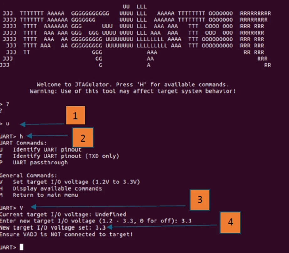
Step 3: Run JTAGulator
Once the dependencies are installed, launch the JTAGulator. Ensure you are in the JTAGulator directory and run the following command:
sudo python3 jtagulator.py
Note: It might be necessary to run the command with sudo to gain access to specific hardware interfaces.
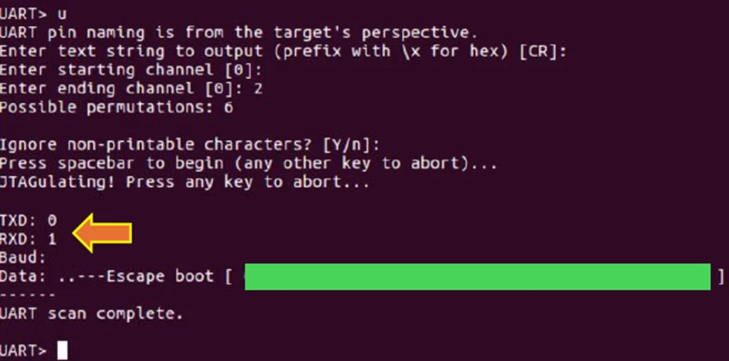
To enhance clarity, I have labeled all the pins for better understanding. The Jtagulator successfully identified UART RX and TX, while also pinpointing JTAG signals such as TDI, TDO, TMS, and TCK. For the ground pin, a simple method involves soldering a pad anywhere on the router and using the multimeter in Continuity mode to verify its connection to the ground.
The designated pins for receiving (RX), transmitting (TX), and ground (GND) are labeled below. These pins are utilized to establish a connection for accessing the command line interface.
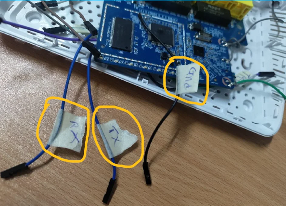
Labeled Pins
To establish a connection to the router, connect the TTL to the USB connector using screen software. Ensure proper connection by confirming that the RX of the router is linked to the TX, and the TX of the router is connected to the RX of the TTL to USB connector.
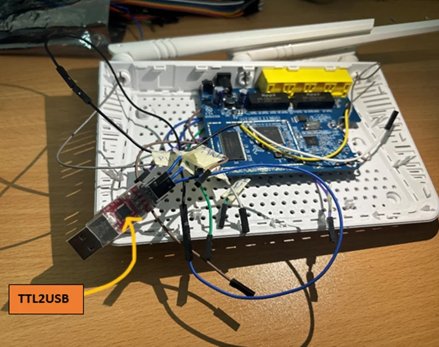
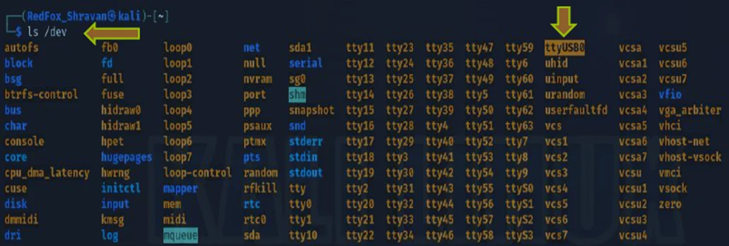
Checking whether the USB (TTL2USB) is connected to our Kali Linux machine as ttyUSB0.
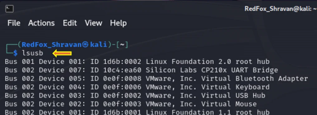
Identifying USB in Kali
Great, we can see that the USB is connected to our system.
At this point, we can initiate the command to establish a connection with the router.
The typical baud rate for most embedded devices is 115200. To confirm the actual baud rate, we employ the baudrate.py tool on the Kali system. Establishing a connection to the UART involves using the command screen /dev/ttyUSB0 115200. It’s essential to power off the device while executing the screen command.
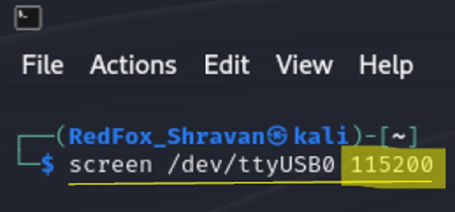
Screen Command line
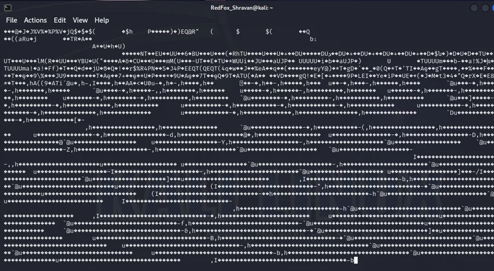
Following the execution of the screen command and powering on the device, it becomes evident that we are receiving incomprehensible data, indicating a misconfiguration of the baud rate.
Gibberish data
To obtain a accurate depiction of the debugging data, we can start by trying other baud rates, beginning with 9600.
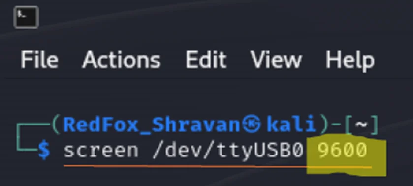
Screen Command with 9600
Selecting a baud rate of 9600 reveals a distinct set of data; however, it remains unintelligible and cannot be interpreted.
Gibberish data
Next, let’s attempt a baud rate of 19200.
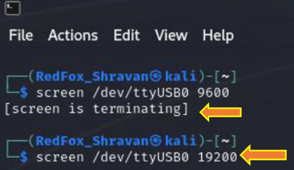
Screen Command with 19200
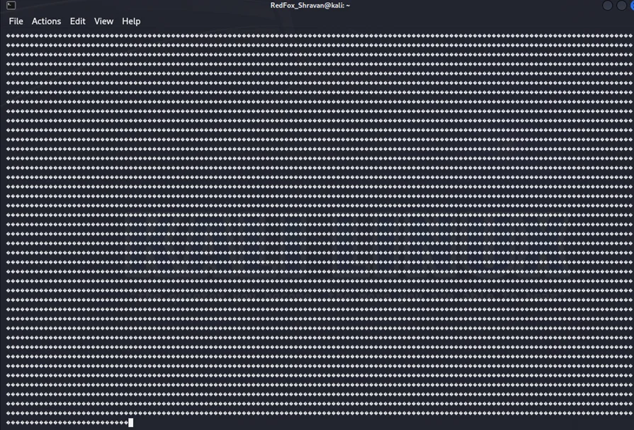
In this instance, no data is being received at the baud rate of 19200.
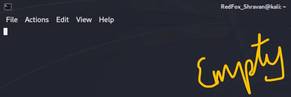
Blank Terminal for output
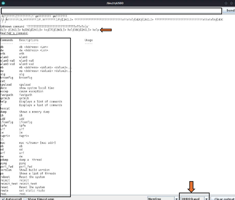
After multiple attempts, the next baud rate we try is 38400.
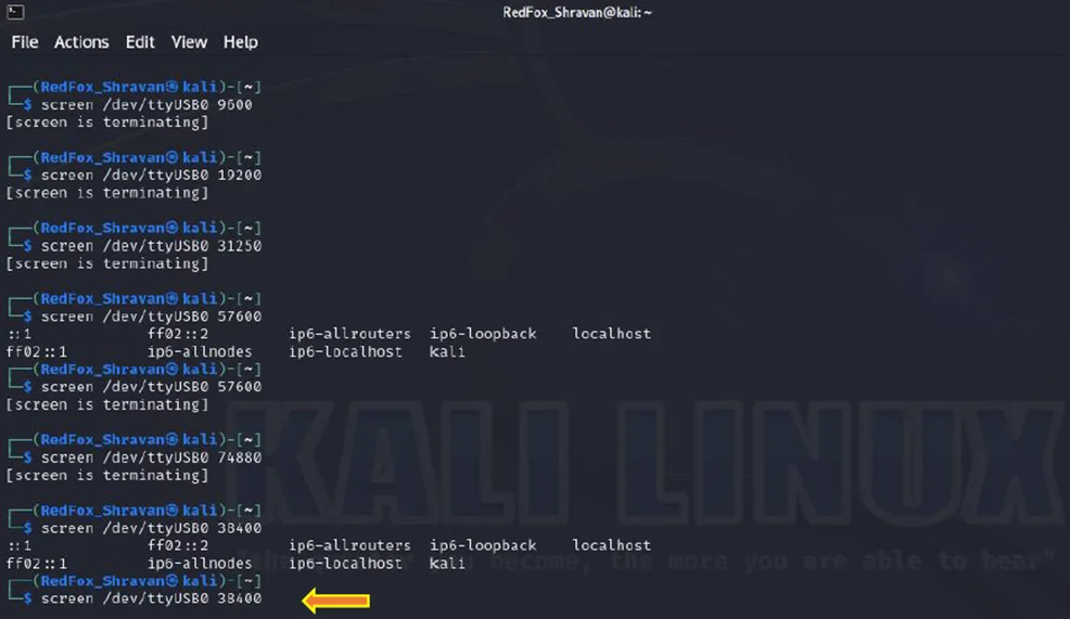
Screen Command with 38400
At a baud rate of 38400, a successful connection has been established, and a set of data has been received. The data is now readily interpretable.
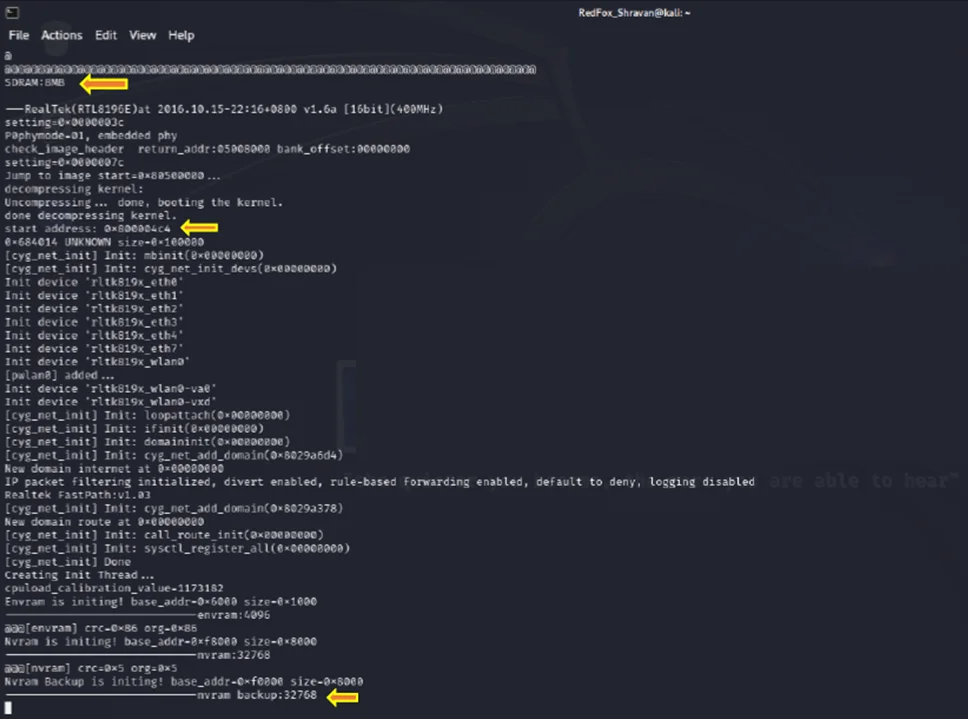
Booting and data in Terminal
In the output, it initiates with the boot process, displaying the message “NVRAM backup initiated” Upon interrupting the debugging process by pressing ENTER on the keyboard, as depicted in the accompanying image, we seamlessly transition into a Command Line Interface (CLI). Within the CLI, we enter a promiscuous mode.
Promiscuous mode is commonly employed for monitoring network activity and diagnosing connectivity issues. In this mode, a network snoop server can capture and store all packets for subsequent analysis.
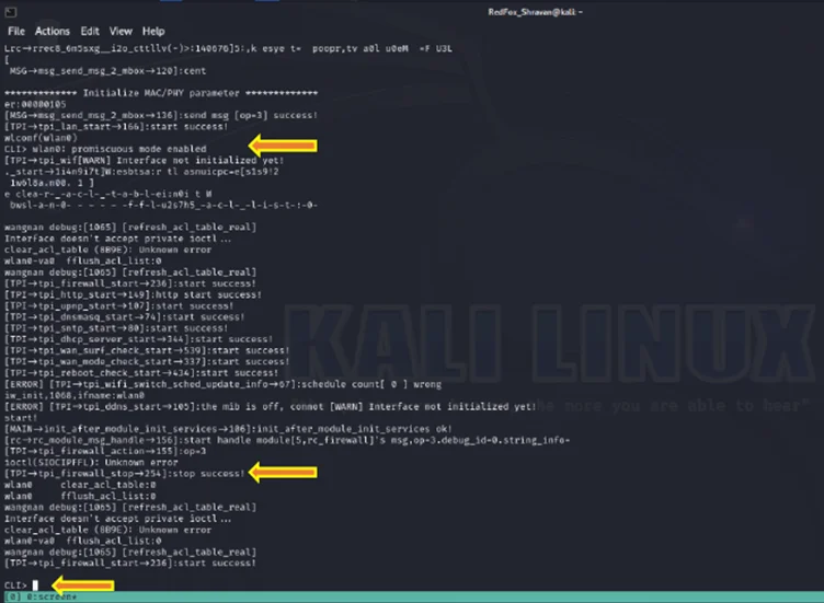
Command Line Interface
Upon encountering the CLI> prompt, an array of commands becomes visible. Noting the presence of “CLI>” in the terminal, entering “help” yields a comprehensive list of available commands.
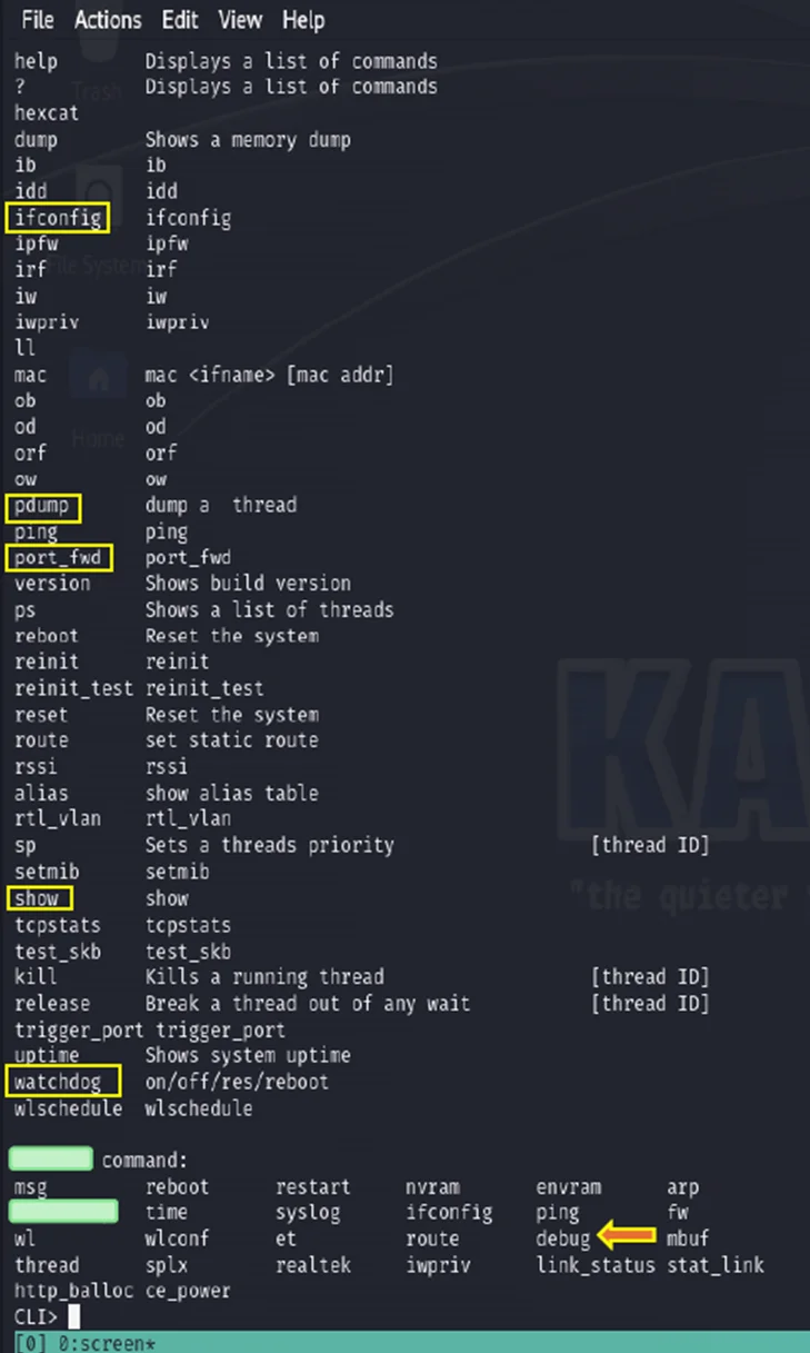
Help command in CLI
Upon executing the “ifconfig” command, the following information is obtained:
					Inet address: 192.168.0.1
Bcast: 192.168.0.255

ifconfig command in CLI
Examining the CLI> syslog command also reveals that debugging messages for the system, Simple Network Time Protocol (SNTP), and the “Syslog” command originate from the outputs, initiating a diagnostic process for these components.
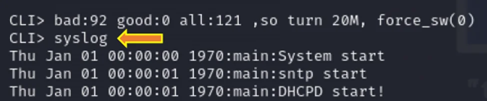
syslog command in CLI
By utilizing the CLI> show command in the CLI, a comprehensive list of additional information about the router is displayed. Furthermore, the output provides details on the processes currently running in the system.
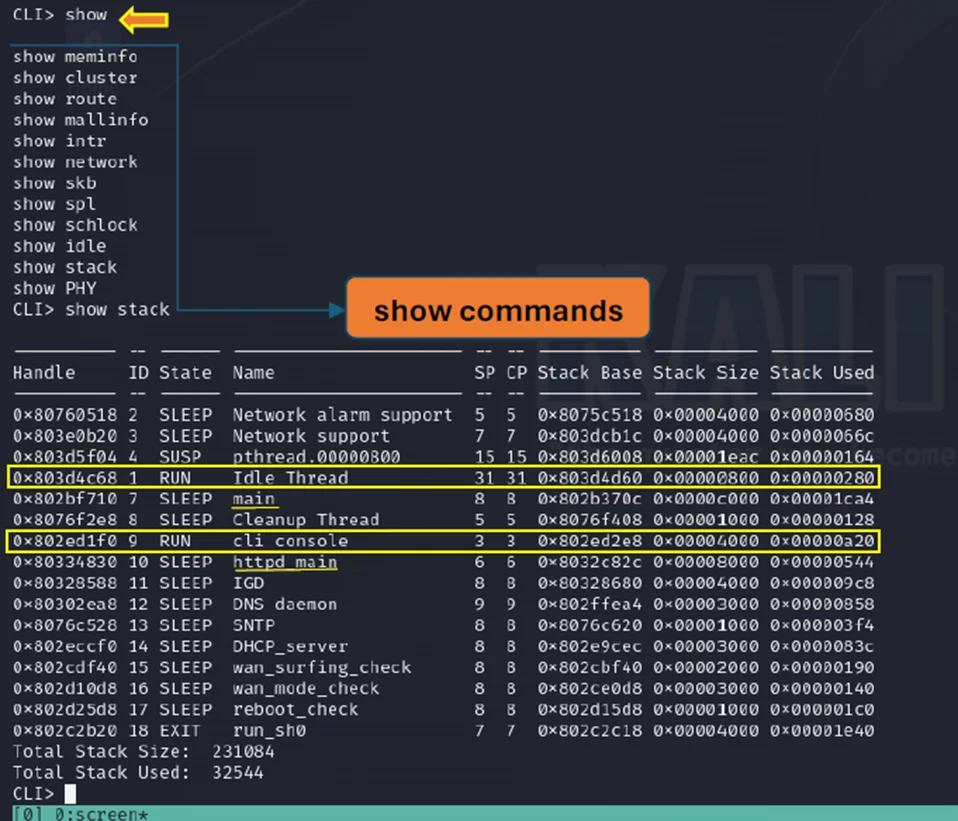
Show command in CLI
Executing the command CLI> realtek reveals details about the chipset. Upon using these commands, networking information, including Ethernet connection, local connections, and bridge connections, is obtained.
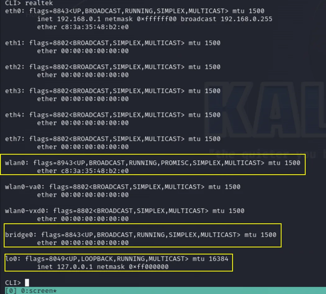
Realtek command in CLI
Next, we proceed to extract data using the command “dump address(size) size length.”
Dump Command in CLI
Unfortunately, we are unable to visualize any hex dump of data for the specified addresses.
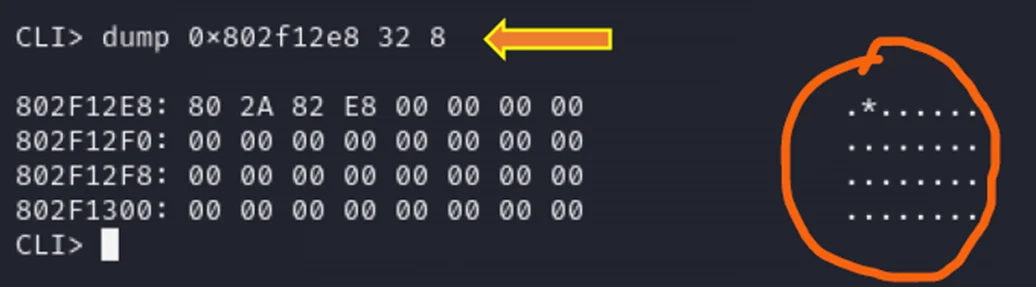
From now on, when using the dump command, let’s specify the limit and try to get data from the memory.
The error “TLB miss (during load and fetch)” occurs when the Translation Lookaside Buffer (TLB) doesn’t have the required translation information for a particular virtual address. This situation prompts a search in the page tables.
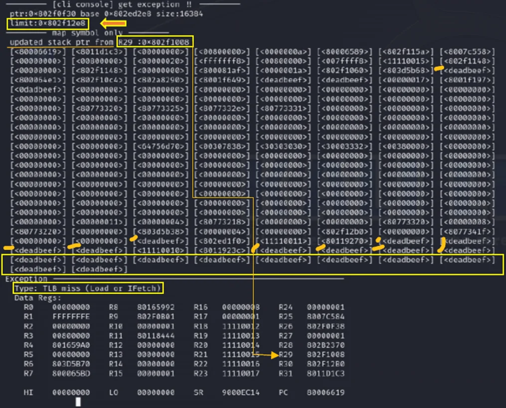
CLI Console with a data limit
At this point, readable data is visible in the dumps.
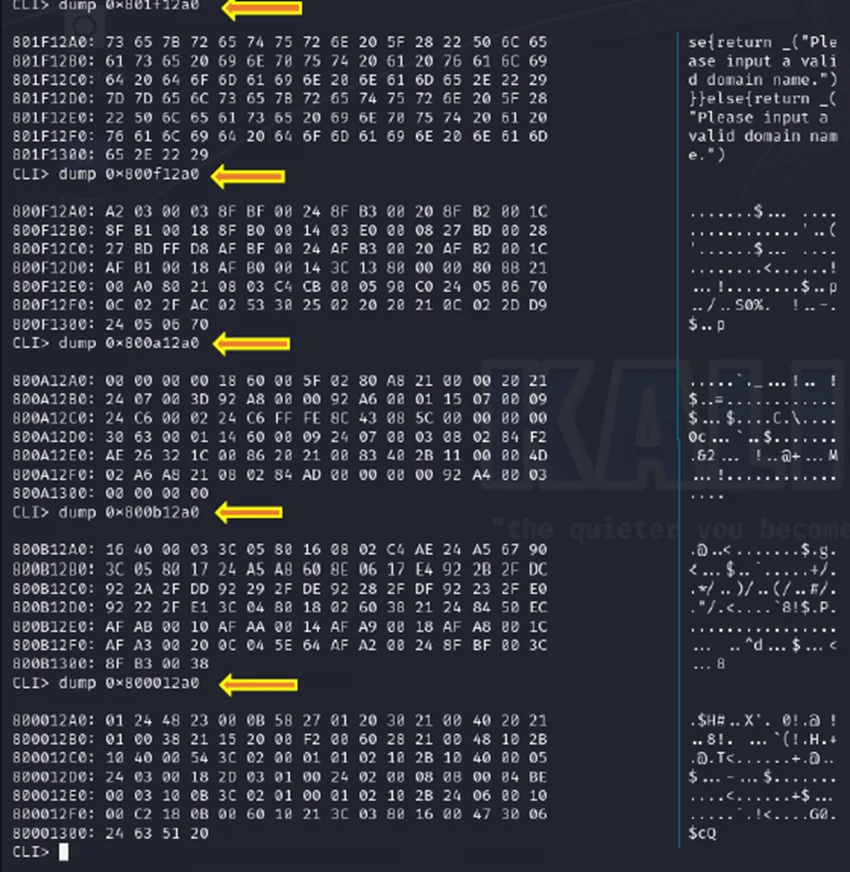
Hexdump Data in CLI
Upon connecting the TTL to USB (Transistor-Transistor Logic to Universal Serial Bus) connector and pressing the Enter key along with a specific set of keywords, you gain access to the <Realtek> console. The display may show a watchdog timeout, and the user can initiate an Escape boot sequence, enabling entry into the Realtek console.
SDRAM: The chipset specifies an 8MB SDRAM before it undergoes a reboot due to a watchdog timeout.
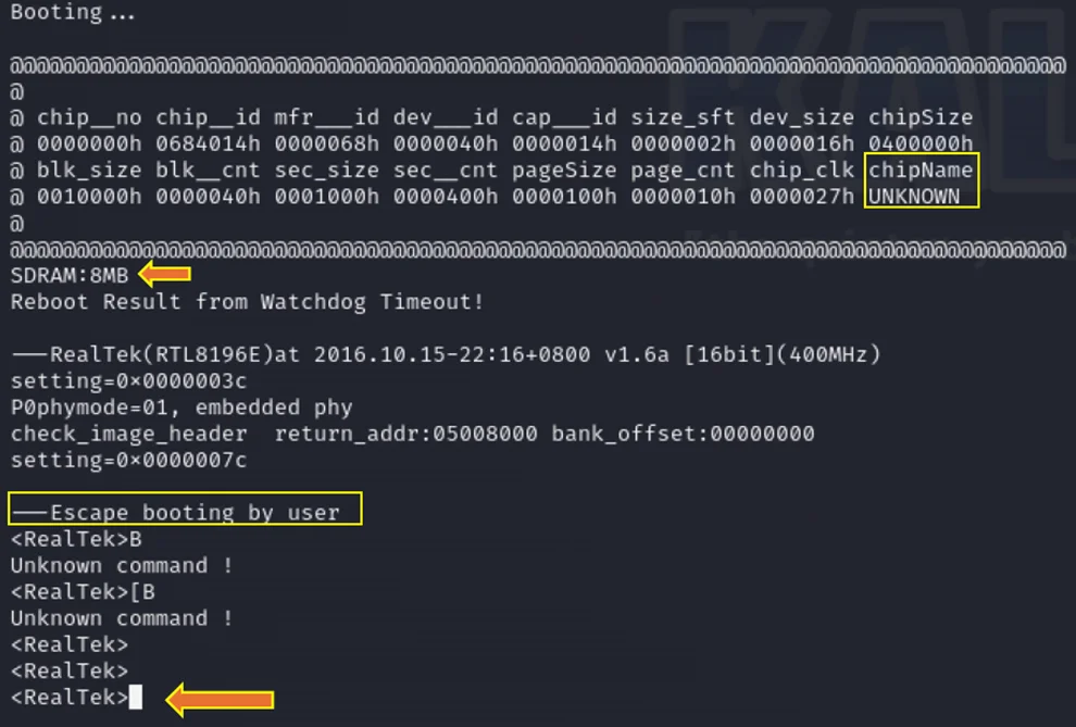
Booting process and Realtek console
For those less familiar with the screen command, an alternative is to utilize the Arduino IDE environment with the appropriate COM port selected. Within the serial monitor, set the baud rate to 38400, and you’ll seamlessly access the CLI, enabling the use of other commands demonstrated earlier in Screen.
In conclusion, this blog provides an insightful walkthrough on exploiting IoT devices through hardware hacking, specifically focusing on UART interfaces in routers. The process involves intricate steps like hardware reconnaissance, identifying and soldering test pins, and establishing a connection using tools like JTAGulator and Kali Linux. It demonstrates how to identify UART pins, connect them using a TTL2USB connector, and utilize various baud rates to access the Command Line Interface. This exploration underlines the importance of robust hardware security in IoT devices, showcasing both the vulnerability of these devices and the methods used for penetration testing and security analysis.
Redfox Security is a diverse network of expert security consultants with a global mindset and a collaborative culture. If you are looking to improve your organization’s security posture, contact us today to discuss your security testing needs. Our team of security professionals can help you identify vulnerabilities and weaknesses in your systems and provide recommendations to remediate them.
“Join us on our journey of growth and development by signing up for our comprehensive courses.”


Redfox Cyber Security Inc.
8 The Green, Ste. A, Dover,
Delaware 19901,
United States.
info@redfoxsec.com
©️2024 Redfox Cyber Security Inc. All rights reserved.